Part 1 – What is a FOWT? Details on the floater and the turbine
Welcome to the WFO Floating Offshore Wind blog series! Over the next weeks, this series will focus exclusively on floating offshore wind by presenting the key technology aspects and innovations required for commercial-scale deployment.
Introduction
Floating offshore wind (FOW) is a relatively new renewable energy technology expected to play an important role in our future energy mix. With a pipeline of multi-hundred to multi-gigawatt projects planned for the next decade, floating wind must make a leap from its current demonstrator & pre-commercial phase into an industrial, commercial-scale era.
As a result of the technology’s current level of development, no country or region yet has an established floating wind supply chain. The presence of multiple floater designs and subsequent mooring and electrical cable configurations introduce many new materials and tools to use. Construction sites and ports for installation and maintenance will have to be capable of building, assembling, and transporting certain types of floating offshore wind turbines (FOWT) including their station-keeping systems (the anchors and mooring lines). Advanced technologies for monitoring will have to be integrated into the design of the FOWTs to ensure their reliability over the project lifetime.
There is one overarching paradox associated with improving the technical readiness levels of FOW. On the one hand, the industry is recommended – by insurers and financers – to borrow as much as possible from lessons learned of previous industries (e.g., bottom-fixed, oil & gas) to preserve risk perception. Yet on the other hand, new technologies are required to realise floating wind at a commercial scale. This first article of the CRASH COURSE – Floating Offshore Wind blog series will break down the main features of “the topside” of the FOWT system, i.e., the floater and the turbine. At the end of this series, we hope that readers will have a more profound understanding of floating wind technology and what is required to make it succeed at a commercial scale.
The topics addressed in this series are also discussed in detail by WFO’s Floating Offshore Wind Committee (FOWC), a forum dedicated to bringing floating wind technology to commercial scale. The FOWC consists of four Subcommittees focused on the following key areas of floating wind: Insurance, Moorings, Operations & Maintenance; Cables & Floating Substations. Click here to learn more about the FOWC and how to join.
The floater
Major designs
Floating wind foundations, or floaters, can be categorised according to their stabilising mechanism:
- ballast stabilised, where the centre of gravity of the total system is below the centre of buoyancy
- waterplane (or buoyancy) stabilised, where a waterplane area serves as the restoring moment
- mooring stabilised, where high-tensioned mooring lines generate the restoring moment.
The prevailing substructure designs rely on the stabilising mechanisms mentioned above are summarised below.

Illustration of prevailing substructure designs (from left to right: Spar, semi-submersible, Tension-Leg Platform). Source: Josh Bauer / NREL. The floaters seen here have strong parallels with floating oil & gas platforms designs. However, new concepts are coming up or have already been deployed.
- Single point anchorage (Spar) buoy:
By using simple and proven technology, the spar buoy has a very low centre of gravity thanks to its long cylindrical structure filled with ballast at the bottom. This implies a large draft, restricting the floater to larger water depths and making it difficult to assemble and install.
- Semi-submersible:
Three columns are situated on the edges of a triangle platform and are partially submerged. The turbine is either placed on one of the columns or on a fourth column at the centre of the triangle. The platform can be used in various water depths and can be more easily assembled and installed. Fabrication is more complex due to the braces that hold together the columns.
- Barge:
The barge is stabilised by a plane-structured waterplane area rather than columns. These floaters have the shallowest draft but as a result have greater motions due to waves. Some designs include a moonpool, a large opening in the floater where a water mass is entrapped in a central well, suppressing wave-induced loading.
- Tension-Leg Platform (TLP):
This is a type of floater that features a central column to support the turbine under which vertical mooring tendons anchor the system to the seabed. This achieves high stability during operation, lower structural weight of the substructure, and a smaller seabed footprint. However, the mooring lines are expensive to install and present higher operational risk in case of a failure.
- Hybrid and multi-turbine concepts:
Some floaters use a combination of the three stability mechanisms mentioned in the previous section to combine their advantages. In addition, one floater may host more than one turbine to reduce floater and station-keeping system costs per turbine as well as increase stability.
Ultimately, the chosen floater design is always dependant on project site conditions, but an easily manufacturable design and robust logistics system at the port side are advantageous considering the industry’s push for commercialisation.
Floater design consolidation for cost reduction
The floating substructure has the largest cost reduction potential. However, the 40+ number of concepts being investigated inhibit fast achievement of high technology readiness levels (TRLs) and industrialisation. Honing in on a select few concepts would allow for targeted design improvements, clarify the supply chain needs for mass production and as a result increase investor confidence. A particular cost advantage of floating wind substructures is that their mass — and hence procurement cost — scales favourably with increasing wind turbine.
In floating wind, industrialisation also concerns mooring and cabling systems as well as marine operations, further underlining the need to consolidate concepts to standardise production and reduce costs. Nevertheless, we can expect the competitive nature of the market to reveal which designs will fare best, especially in anticipation of the learnings from the upcoming pilot/pre-commercial projects and the strategic partnerships for the later commercial-scale projects.
Materials used for the floater
Across all designs, today’s floaters use either concrete or steel, or a combination of both materials. Generally, semi-submersibles require steel while barges and spar require concrete. However, many of the floating concepts can be built almost interchangeably in concrete or steel. For example, BW Ideol deployed two prototypes made each of predominately steel or concrete. The Hywind Pilot Park used a steel spar and now the Hywind Tampen park under construction is using concrete to reduce costs.
Table 1. Generalised advantages and challenges of steel and concrete floaters
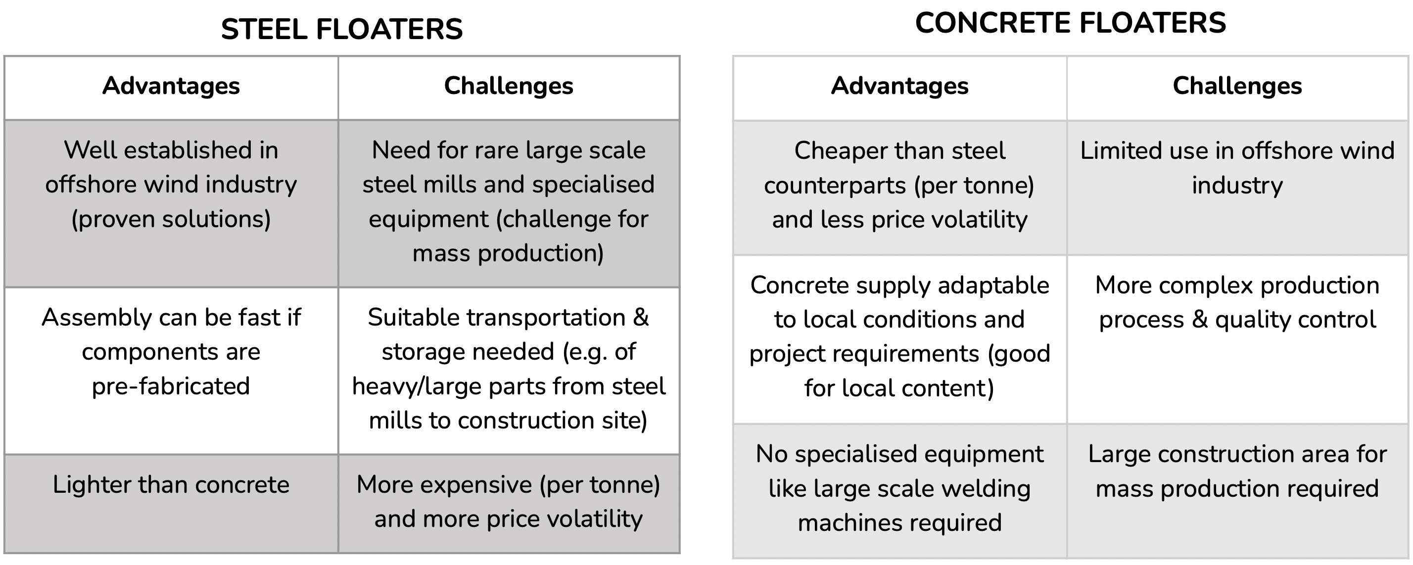
Source: Mathern et al. 2021; Matha et al. 2017. Ultimately, the decision to use either or a combination of materials comes down to the individual project. Many floater concepts can be adapted to be built using either concrete or steel, depending on other factors such as the local market or stakeholder preferences.
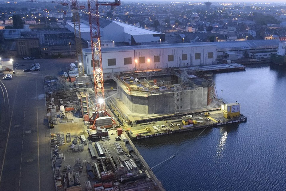
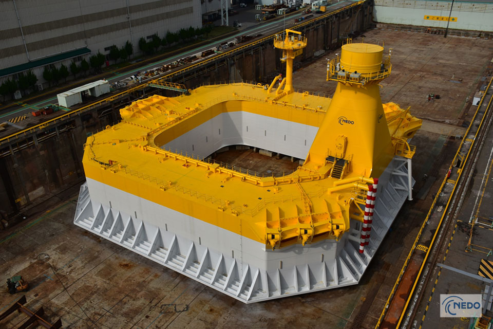
Top: BW Ideol’s Floatgen prototype of 2 MW commissioned in 2016 off the coast of France under construction. The floater was erected with concrete on top of 3 interconnected barges moored at the quayside. Once the construction complete, the floater was released after towing away the barges temporarily and submerging them. Bottom: BW Ideol’s Hibiki prototype of 3 MW (also known as Kitakyushu demo) commissioned in 2018. The foundation is predominately made of steel and was fabricated in a dry-dock by assembling blocks made of steel plates that have been cut and welded together. The floater was released by flooding the dry-dock. Source: BW Ideol / Bouygues Travaux Publics / Devisubox (top); NEDO Website (bottom)
While steel has dominated the offshore wind industry in the past decade, the use of concrete for future offshore wind farms is likely to increase. According to DNV, concrete floaters are an attractive alternative to steel floaters from cost and carbon footprint comparisons. In a 2016 study by Ideol that compared concrete and steel versions of their floater for a 6MW turbine, the concrete design was associated with 50% lower material costs than the steel alternative and led to 40-50% lower greenhouse gas (CO2e) emissions. DNV recently launched a joint industry project on the use of concrete for floating wind, with the aim of enabling more efficient use of materials whilst maintaining the historically robust performance of offshore concrete structures.
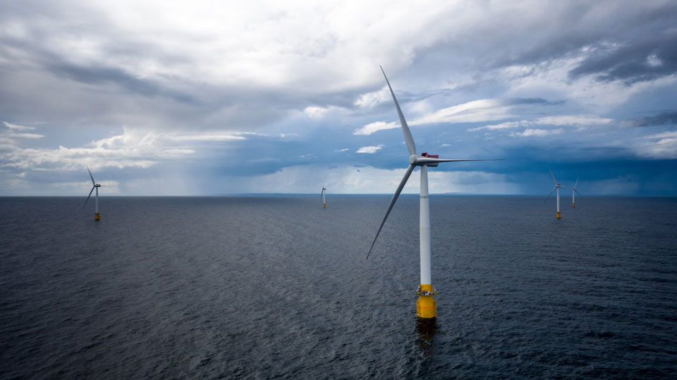
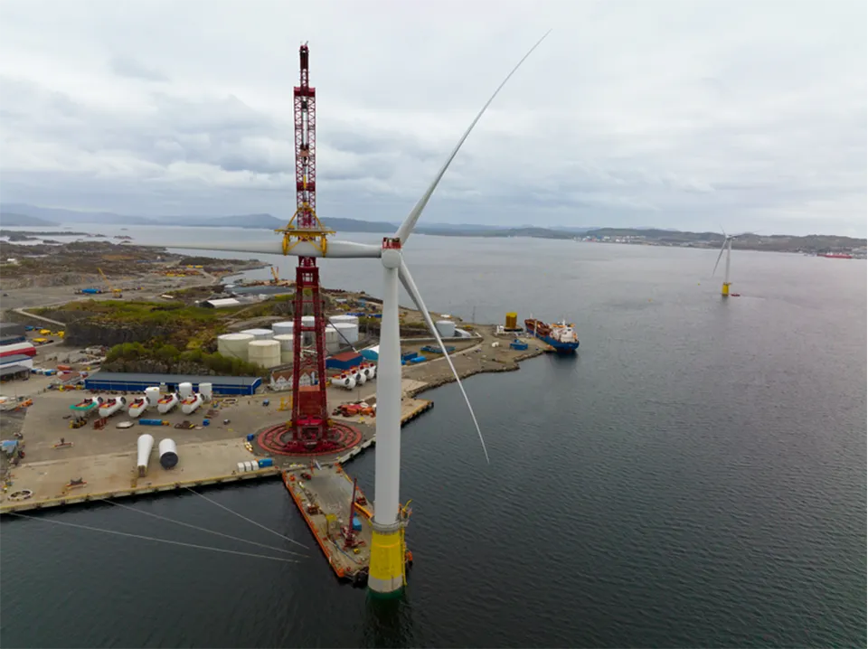
Top: Hywind Scotland in operation, using steel foundations. Bottom: Hywind Tampen under construction, using concrete foundations. Source: Øyvind Gravås/Woldcam/Statoil ASA (top); Jan Arne Wold/Woldcam/Equinor (bottom)
R&D on high performance of both materials is underway to improve their function for floating wind foundations (e.g. special concrete, special steel). Additive manufacturing through 3D printing is also being explored for floaters to eliminate conventional manufacturing limitations.
The complexity of structures will increase with the development of hybrid systems. Associated evolutions in material choice offers great opportunity for project sites to coordinate with local capacity, especially now that local content is a priority for governments to reach their floating wind targets. However, costs need to be minimised for the technology to remain politically and economically viable. In addition, risk management remains paramount to avoid unforeseen problems that can cause production delays and lead to additional costs.
Ultimately, the decided floater concept and associated material is based on specific conditions of the project such as water depth, geo-technical conditions, wind turbine type etc. Supply chain capability, production and installation processes, structural design, and durability aspects (especially in the context of risk management) also influence this case-by-case decision.
The turbine
Given the world’s brief experience with floating offshore wind, the industry is currently using bottom-fixed offshore wind turbines with some minor modifications, e.g., at the tower and control system. Conventional turbines will continue to be used even for commercial-scale projects given existing project experience and the reticence of Original Equipment Manufacturers (OEMs) to specialise in floating offshore wind right away. Nonetheless, some turbine suppliers are already looking into floating-wind specific turbine designs. For example, GE is developing a 12 MW concept where the control system is co-designed with the tower and platform in order to achieve a 35% overall weight reduction. Similarly, MingYang Smart Energy is developing a lightweight, anti-typhoon 16 MW turbine.
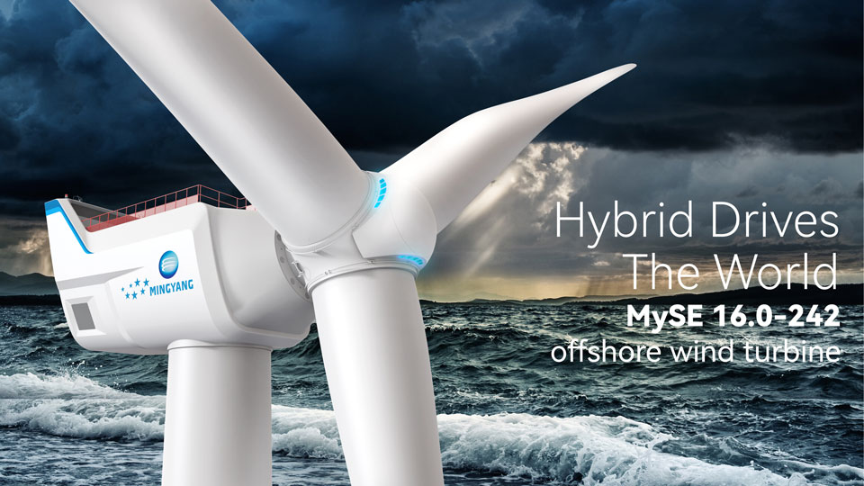
The MySE 16.0-242 turbine, one of the upcoming 15+ MW models in the market. A single MySE 16.0-242 turbine can generate 80000MWh of electricity every year, enough to power more than 20000 households. Source: MingYang Smart Energy
With increasing operational experience, however, our understanding of WTG components’ sensitivity to floating-specific effects will improve and inform any other potential modifications. Research by the Carbon Trust already shows that motion and structural dynamic characteristics can be better accounted for in the future, and existing modifications in the tower and control system will be key to pursue as they are most affected by the floater.
Across both bottom-fixed and floating wind, one obvious evolving characteristic for FOWTs is the unit size: the future of the industry can anticipate 15 MW turbines to be used by 2030 and 20 MW closer to 2040. The scaling of turbines is considered a key driver of cost reductions for the industry, with floaters identified as scaling favourably with increasing turbine size.
The tower of the wind turbine is generally made of tubular steel sections that are more easily recyclable while the blades are made of fiberglass or carbon fiber held together with resin. These materials are harder to recycle. Recyclable materials for turbine components are being developed in bottom-fixed wind and could see their adoption in floating wind as well. At the moment, three of the 38 turbines installed for the Kaskasi bottom-fixed wind farm in the German North Sea are using recyclable blades produced by Siemens Gamesa (all turbines are set to be operational by the end of 2022). The 1.5 GW bottom-fixed offshore wind farm Hollandse Kust Zuid (HKZ) being built off the coast of the Netherlands is also set to use these recyclable blades. The blades will use a resin type that would facilitate the separation of blade components during decommissioning and eventually their recyclability.
As with floaters, additive manufacturing through 3D printing is also being explored for turbine components: GE Renewable Energy is researching how to 3D-print the concrete base of wind turbine towers to enable wind farms to concentrate their production at their sites.
Lastly, besides adaptions to the physical turbine, the monitoring environment will also necessitate upgrades to accommodate our understanding and improvement of FOWTs, especially at a commercial scale. There will be a need for computing power to design future FOWTs and eventually model their real-time behaviour for project and industry data. For example, new remote techniques like “lidar” (Light Detection and Ranging, a method that uses pulsed lasers to measure ranges) can provide information to the wind turbine control system and enable it to adapt to the current wind situation in time.
Design interface between the turbine and station-keeping system
On this last topic of designing and modelling FOWTs, there is currently a disconnect between the turbine and floater R&D. From a technology standpoint, analysis software used to simulate realistic behaviours of floating wind systems need to be able to integrate both the turbine and its station-keeping system in a way that does not sacrifice on accuracy and can cover multiple units. In developing digital twins (models that infer real-time information from indirect measurements), it will be critical to solve issues on data sharing and ownership between multiple stakeholders. From a commercial standpoint, manufacturer acquisitions and technology partnerships can enable the design and supply chain consolidation necessary for commercialisation where a select number of designs would be able to support themselves through the necessary R&D and secure investor confidence.
Preview of the next article
There are significant infrastructure requirements associated with the manufacturing and installation of floating offshore wind foundations. In the next blog, we will provide an overview of the fabrication and installation phases of FOWTs.
Update November 10th : Categorisation of floaters re-formatted in Major designs as well as Table 1 updated in Materials used for the floater.