Cover photo source: Saitec Offshore Technologies
Part 3 – FOWT Moorings & Anchoring
Introduction
In our last blog article, we detailed the fabrication and installation activities of floating wind turbines occurring at the port. If you have not yet checked it out, click here.
In this article, we will dive into the designs and innovations related to moorings and anchors for floating offshore wind.
Floating Foundations
Floating foundations open the way for generating power from deeper waters, which can unlock new sites that today’s bottom-fixed offshore wind turbines could not access. The main floater design concepts are derived from the offshore oil and gas sector where they are deployed commercially (and at a large scale). As detailed in our previous articles, there are 4 main categories of concepts that are deployed (or about to be deployed). New “out-of-the-box” designs are also underway, with their main goal being to better target floating offshore wind conditions and mass production requirements.
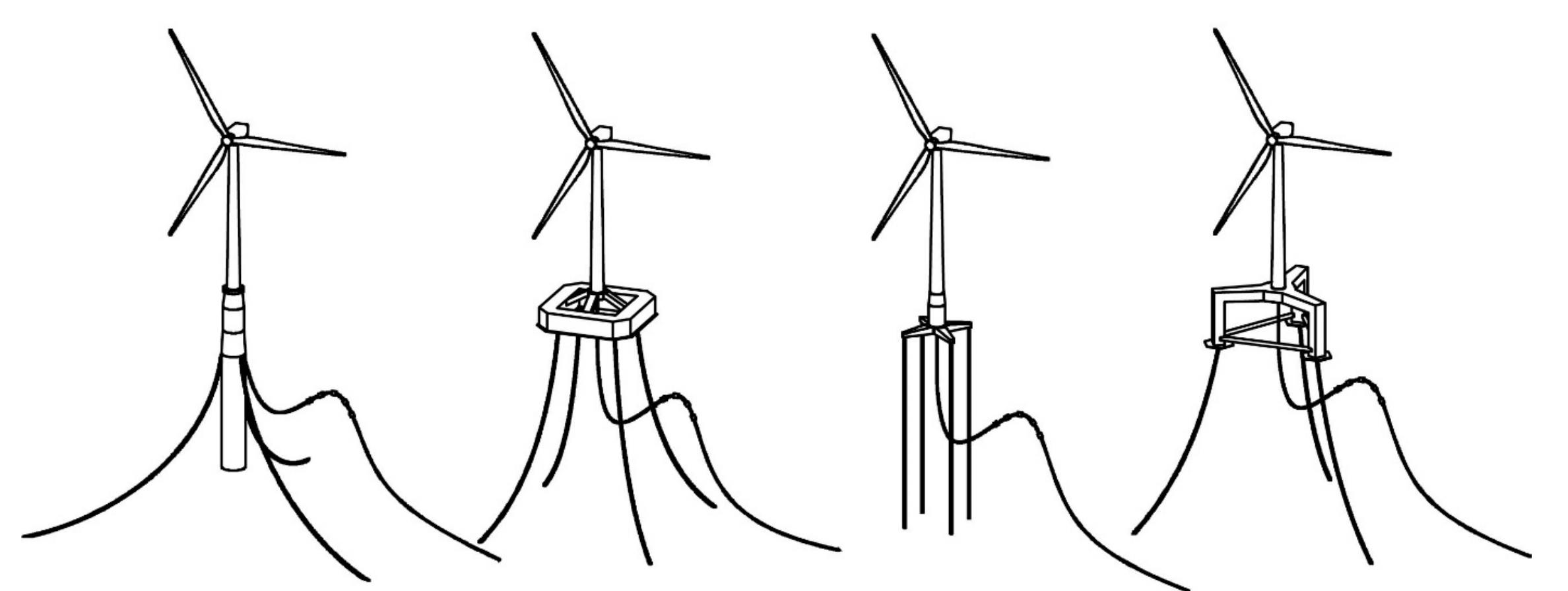
Figure 1. Spar, Barge, TLP, Semi-Sub (from left to right). Source: Scheu et al. 2018
Featured in Moorings White Paper
Purpose of a Mooring System – Station-Keeping
The purpose of any mooring system is to maintain station and control motions of the floater. Station-keeping means maintaining a floating structure in a fixed position relative to a fixed point or within a defined sector relative to the fixed point. The station-keeping system of a floating offshore wind turbine (FOWT) includes the mooring lines or tendons, as applicable, as well as the anchor foundations that transfer forces from the system to the seabed. It is critical that station-keeping protect the dynamic power cables from damage by floater motions.
Individual mooring configuration will depend on the specific site conditions, selected floater, power cable dynamic configuration, cost reduction requirements, local logistic capacity etc. This in turn will impact how the floating foundations behave, which can be described as being either ‘compliant’ or ‘restrained’ with respect to global motions i.e. the ‘six degrees of freedom’ (Table 1 below).
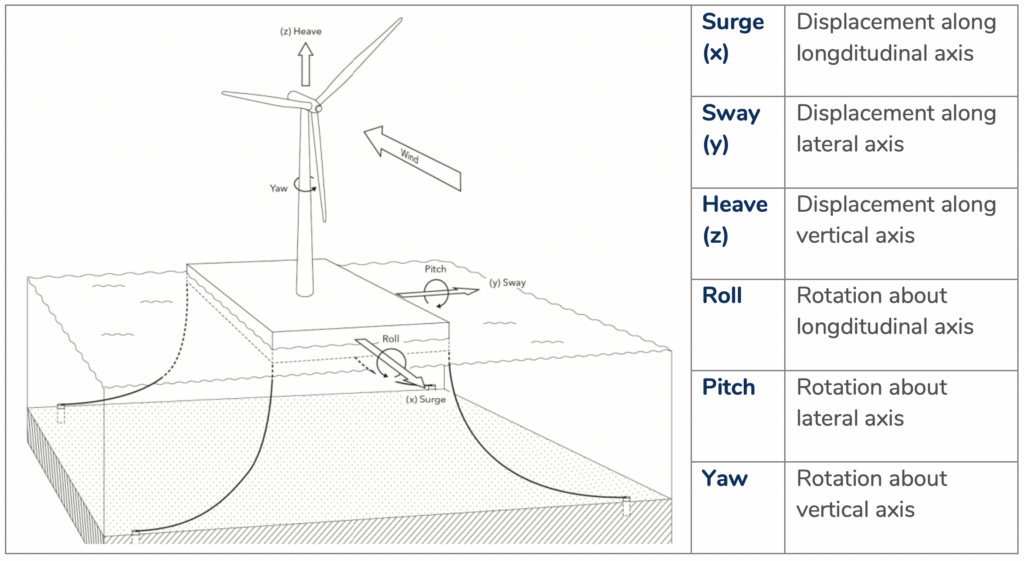
Table 1. The six degrees of motion for a FOWT. Source: DNV
Featured in Moorings White Paper
Compliant mooring systems cause a level of excursion of the floater. A softer compliance means greater excursion of the floater, whereas a harder compliance restricts the excursion but results in higher mooring loads, especially in shallow water. Typical station-keeping systems of compliant floaters are based on catenary, taut, or semi-taut mooring lines. While there are variations among these types, the labels mainly describe the material used on the mooring line. For instance a pure catenary system consists of chain and compliance is achieved through its weight as opposed to its strength. Taut systems are made up of rope and its visco-elastic properties provide the compliance. A combination of rope and chain can be used in a buoyant semi-taut system.
A Tension Leg Platform (TLP) floater (refer to the first article of this series) is the only type with a constrained mooring configuration (so not compliant). The mooring system is made up of tendons that are perpendicular to the floater/seabed (not shown below).
The naval architect’s decision therefore is how to tune/balance these responses with respect to floater type, mooring configuration and mooring line make up.
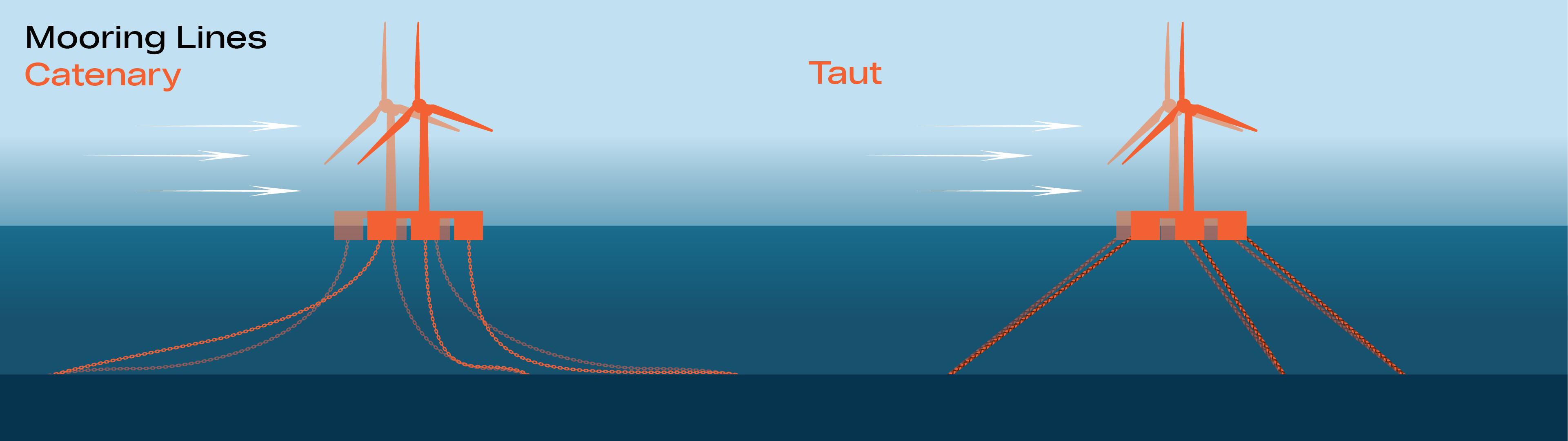
Figure 2. Catenary and taut mooring configurations. Source: BBRG
We can see in Figure 2 that each mooring line connects to a different point on the floater, which is characteristic of a spread moored design. This mooring design fixes the floater in a specific position. However, a different type of mooring configuration, the SPM/turret type, has all the mooring lines connect to one point at the floater and enables the latter to weathervane/rotate with respect to prevailing conditions.
Design Basis for Mooring System
While mooring systems may vary from project to project, they must meet applicable design standards. There is no global governing standard for floating wind, and so each of the classification societies has its own standards which are typically adopted from oil and gas. Each floating offshore wind mooring design will have to comply with prescribed limit states as defined by each classification agency:
- Ultimate Limit State (ULS) – maximum structural stiffness or load-carrying capacity of the intact system beyond which the probability of failure is unacceptable
- Fatigue Limit State (FLS) – maximum stress concentration or damage accumulation, resulting in structural failure due to cyclic loading below the ULS
- Accidental Limit State (ALS) – the minimum survival condition required to maintain structural integrity in a damaged condition (transient and stationary), or in presence of abnormal environmental conditions
Redundancy in Station-Keeping
According to DNV, redundancy is the ability of a component or system to maintain or restore its function after a failure of a member or connection has occurred. For FOW, the definition of redundancy remains a little unclear, with either a strengthening or alternate load path approach being taken with respect to the ALS case. The alternate load path approach could mean the incorporation of multiple mooring lines at individual anchor points (i.e. 3×2 vs. 3×1 configuration), and the strengthening approach would require the increasing of the size of equipment (as opposed to duplicating equipment of the same size).
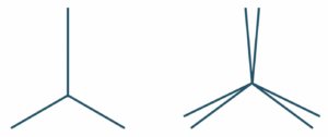
Figure 3. Typical semi-sub 3×1-Line and 3×2-line mooring spreads, seen from above (from left to right)
Designers must balance between “over-engineering” systems with multiple redundancy factors that could meet safety factors but drive-up costs, and “optimisation” which may reduce costs but could lead to larger consequences in the event of a failure (e.g. loss of position or possible collision with adjacent structures, and/or damage to power cables).
Innovations
New technologies (innovations) and new applications of existing technologies (product extensions) are essential to realising floating wind at a commercial scale. It is essential that these products achieve sufficient technological readiness levels (TRLs) to secure sufficient project financing and insurance coverage.
The maturity of a technology can be evaluated on a “readiness level” scale, with levels progressing from a concept backed by desk research to a full-scale prototype test and finally field application. For example, NASA has its own TRL scale. Within the WFO Subcommittees, the API 17N scale for subsea technologies in the oil & gas industry is adopted.
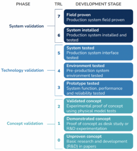
Table 2. TRL for Subsea Technology Readiness Level Assessment. Source: API 2009
The process to achieve the lower TRLs, say from the desk study to advanced computer modeling and test tank prototype (TRL 1-5), is relatively straightforward. Qualifying technologies on a full-scale demonstrator (TRL 6) to deploying them at a fleet level (TRL 7) is more challenging. One first needs the opportunity to work at full-scale, but there are many technologies currently competing for deployment on existing demonstrator FOWTs. For a technology to be field proven (i.e. on a commercial, multi-turbine wind farm), it needs to be able to achieve many hours of operation. Reaching TRL 7 for one given project location may not mean that it is considered at the same level for another location or system.
Synthetic Fibre Rope
Chain for moorings has a long application in human history, and it will be used for floating wind as well. However, just as for oil & gas platforms, synthetic fibre ropes are emerging as another material choice. Compared to chain, synthetic fibre ropes have no corrosion issues, a superior fatigue performance and lower observed failure rates. They are cost-effective, suitable for mass production and have good transportability (as they are lightweight). Polyester is the most commonly used synthetic fibre for offshore moorings.
Synthetic fibre ropes have been adopted successfully by FOWT developers in several demonstrator projects and are undergoing further qualification for shallow water environments (60-200m as defined loosely in the Moorings Subcommittee).
Still, there are some specific design issues which need to be addressed –
- Marine growth, a highly localised issue in which the growth of marine organisms within the top 30m of water can result in different kinds of damage to rope and can add weight to the mooring line, affecting its overall response.
- Seabed contact resulting in materials ingress, accelerated wear and/or abrasion.
- Mechanical damage, being responsible for 100% of failures observed in polyester ropes (for example fishing gear that cut through the mooring line). The lines may be protected against this by cut-resistant jackets.
Load Reduction Devices (LRDs)
LRDs are usually incorporated in the upper section of the mooring line to provide additional compliance in a passive, non-linear fashion, thereby reducing peak loads and fatigue stress on the mooring lines. Using LRDs could reduce the length of cable/synthetic rope required, thereby reducing costs and supply chain pressures.
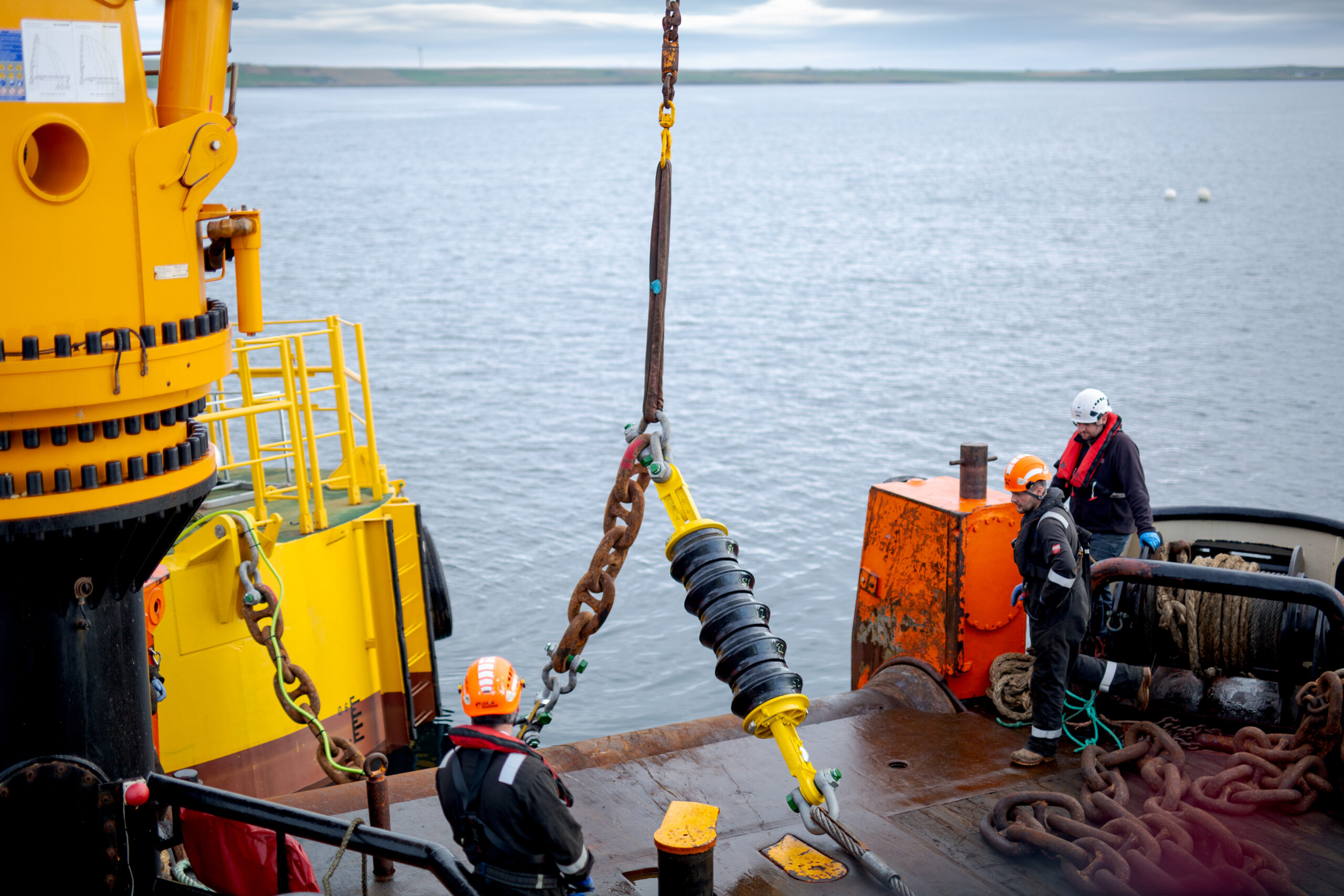
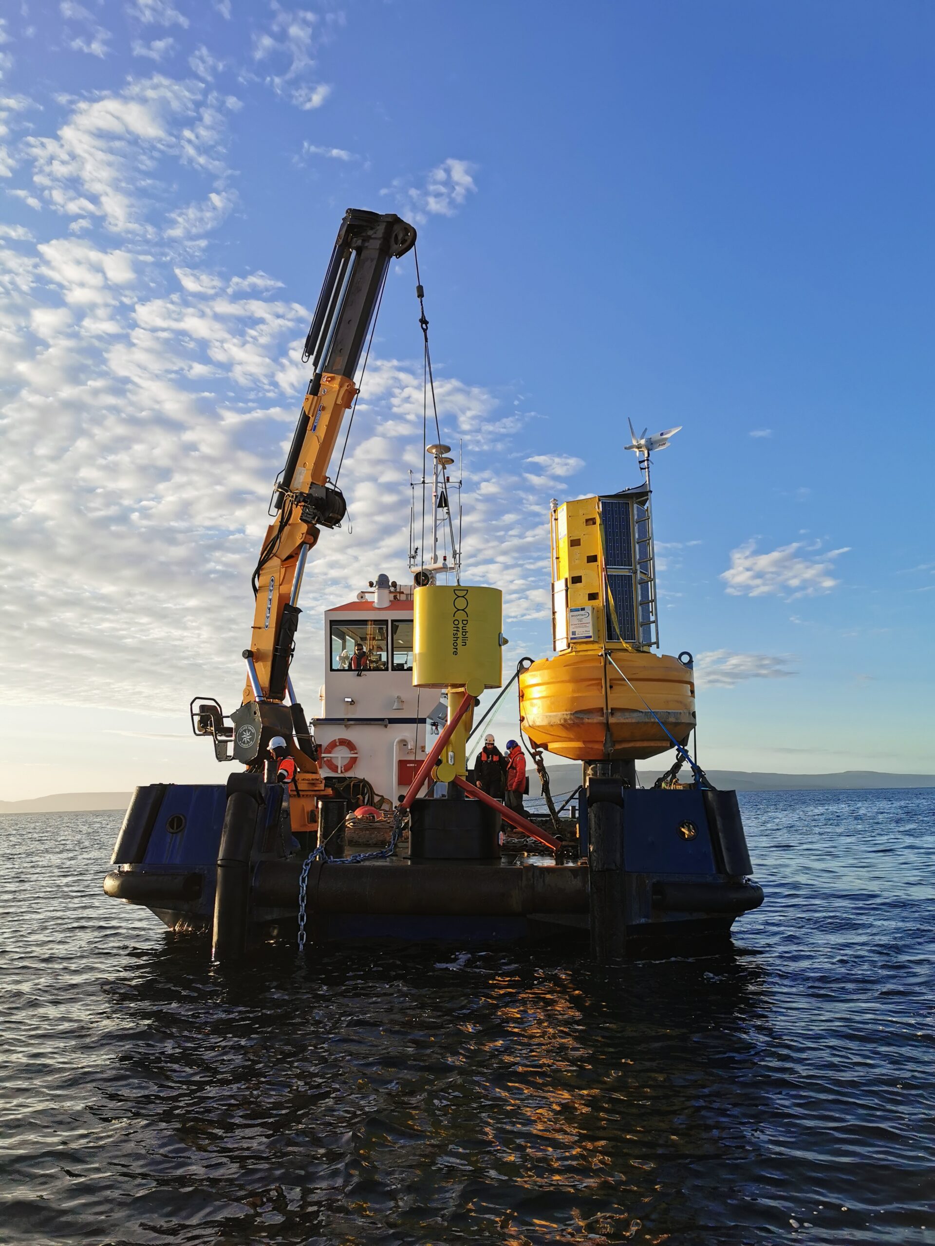
Figure 4. Two types of load reduction devices. Source: Tfi Marine (left), Dublin Offshore (right)
Digital Twins
In short and simple terms, a digital twin is a virtual representation of a real-world asset. In floating wind, a series of sensors are placed at important points of both the topside and subsea elements of the FOWT to create a “digital replica.” Inferring mooring failures from vessel position data is also possible, as done in the oil & gas sector.
The digital replica combines real-life data from the sensors as well as modeling to infer loads, fatigue, wear etc. of the unit or wind farm. By getting an accurate understanding of how the system is behaving, the operator could catch anomalies and based on this information, inspection or maintenance activities can then be scheduled as necessary and around favourable weather conditions. Solving issues on data ownership and sharing between multiple stakeholders will be critical for developing fully integrated digital twins, i.e. where components are monitored and modeled in detail, individually and in relationship to each other.
Product Extensions
Tensioners are used to facilitate, quicken and improve the safety of mooring line installation and tension adjustment. New products include tension and length adjustment equipment permanently installed in the lower portion of the mooring line, e.g., ground chain.
WFO’s O&M Subcommittee identified the need for plug-and-play equipment to facilitate mooring line and dynamic cable connection/disconnection. Different products are being developed to facilitate connection and storage of the mooring lines when disconnected from the FOWT (e.g. by plugging the mooring lines into a buoy to keep them in suspension rather than lay them on the seabed). Connectors are also being developed for cables, although the electrical aspect adds a layer of complexity to the technology. One idea is to combine the moorings and dynamic cables in one simple connection directly at the floater and include buoyancy for wet storage during disconnection of the FOWT.
Figure 5. Example of mooring line tensioner. Source: Vryhof
Mooring Integrity Management
The first White Paper of the Mooring Subcommittee provides a more detailed overview of the topics mentioned in this article thus far, placing the Integrity Management framework as central to the design, manufacturing, installation and operation of floating offshore wind mooring systems.
It is natural to assume that failures in floating offshore wind will occur given the use of new technologies and new serialisation procedures. As such, projects will have to plan for failure but also establish a mooring integrity management (MIM) process that can ensure the moorings’ fitness-for-service over its entire life cycle. MIM programmes categorise risks based on their likelihood and severity, which then guide the use of inspection and monitoring to detect abnormal conditions or factors outside the original design envelope. Should an issue arise, intervention and repair procedures should be enacted to protect the mooring system against accident or loss. Click here to read the Moorings Subcommittee’s White Paper for more details on the topic.
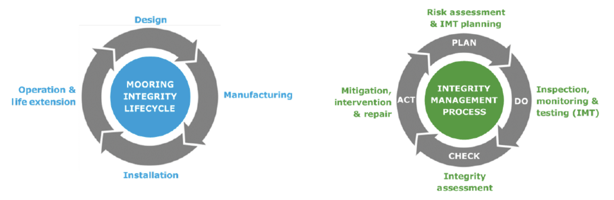
Figure 6. Mooring System Life Cycle (left) and Integrity Management Process (right). Source: DNV.
Featured in Moorings White Paper
Anchoring
There are a variety of options with respect to anchors for floating structures that need to be moored (Figure 7). The selection of an anchor design will be based on local soil conditions (sediment, rock…) and has a bearing on the mooring system configuration.
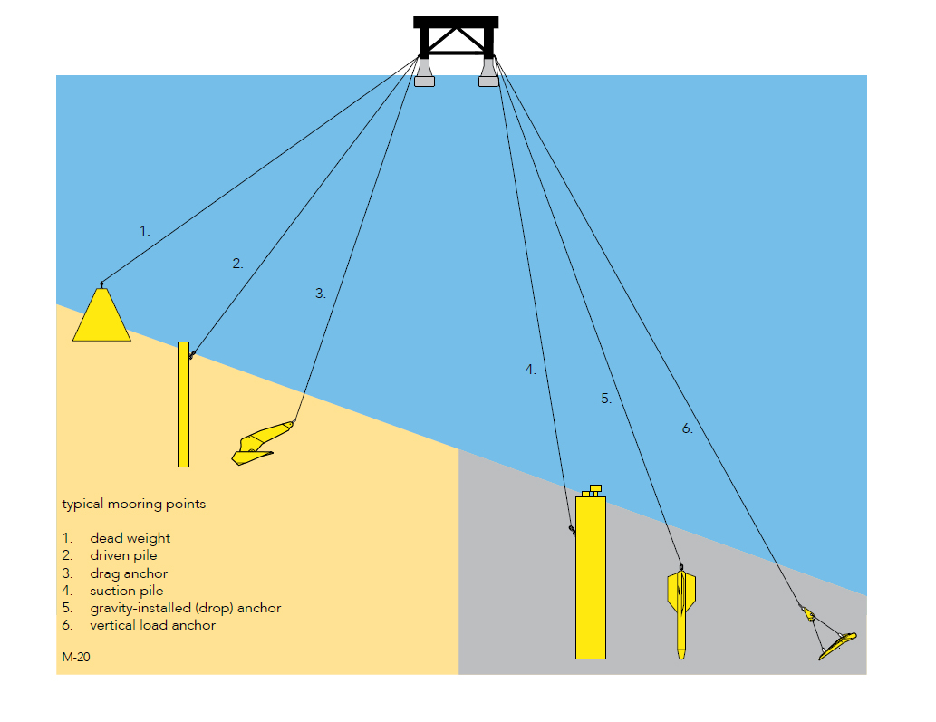
Figure 7. Anchor types for floating structures. Source: Vryhof
Drag embedment anchors are a common choice for floating wind. These anchors drag and penetrate the seabed and can resist large horizontal loads. However, its main limitation is in withstanding vertical uploads, which is why for some floating wind mooring configurations other options could be more suitable. For example, driven piles are installed deep into the seabed using a hammer. Suction caissons drive the anchor into the seabed with a depressurisation mechanism and can be recovered after installation.
Innovations in the Anchor Field
The current anchoring options are mature, but they also need to be viable for large scale commercial wind farms. Innovative anchor concepts will allow for denser spacing of FOWTs and help the mooring system be more cost effective.
These innovations are approaching the offshore business (so not just floating wind) to address existing limitations, i.e. target formerly inaccessible sites (rock, sandy soil), manufacturing drawbacks (modular assembly) and environmental impact (smaller footprint, material choice, silent installation…).
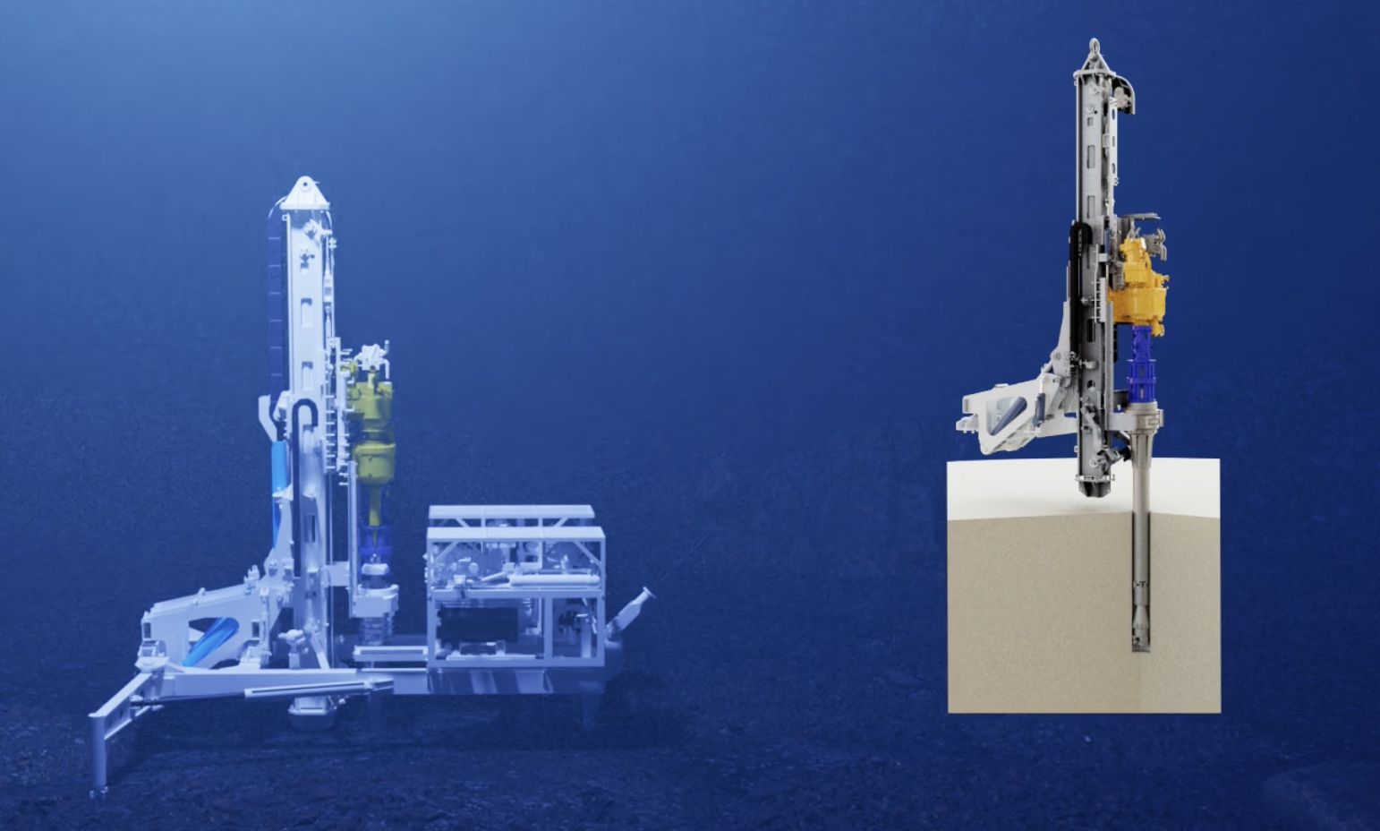
Figure 8. Example of new anchor type – rock anchor (in installation phase). Source: Swift Anchors
Shared Anchors
Shared anchor systems, where multiple floater lines are connected to one anchor, are currently being developed. For example, Equinor’s Hywind Tampen project will use 19 anchors for 11 turbines, which is less than the earlier Hywind Scotland project that used 15 anchors on 5 turbines. However, anchors will need to resist multiple-directional loading and the impact on soil capacity.
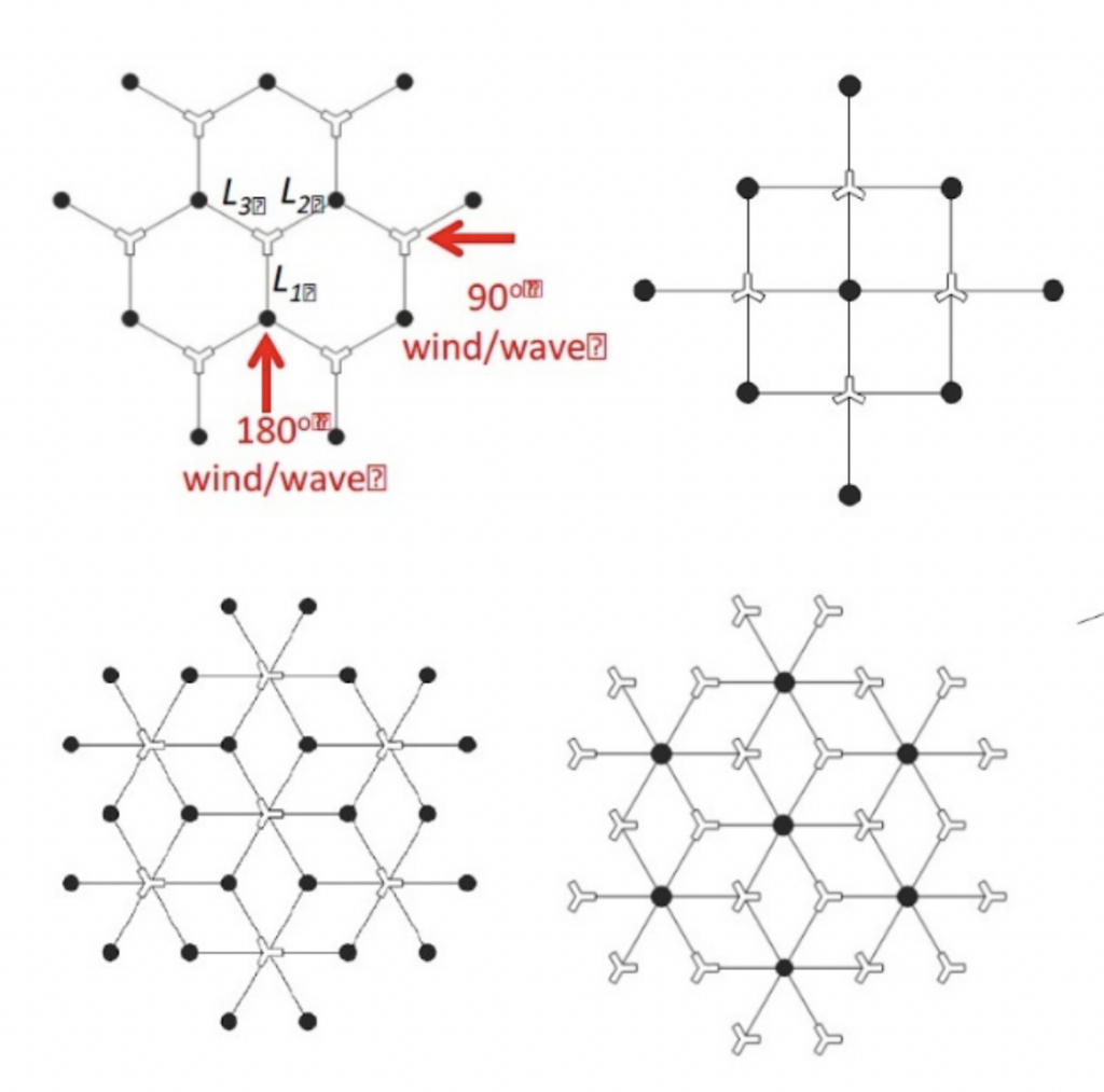
Figure 9. Shared Anchor Geometries. Source: Fontana et al. 2016
Featured in Moorings White Paper
Remote Survey and Inspection for Moorings and Anchors
FOWTs are unmanned stations. Performing routine inspections on hundreds of units at a distance and in harsh weather conditions poses logistical and safety challenges. Carrying out inspection work remotely is therefore necessary and can be done by deploying marine autonomous systems such as Unmanned Surface Vehicles (USV) or Remotely Operated Underwater Vehicles (ROUV or ROV).
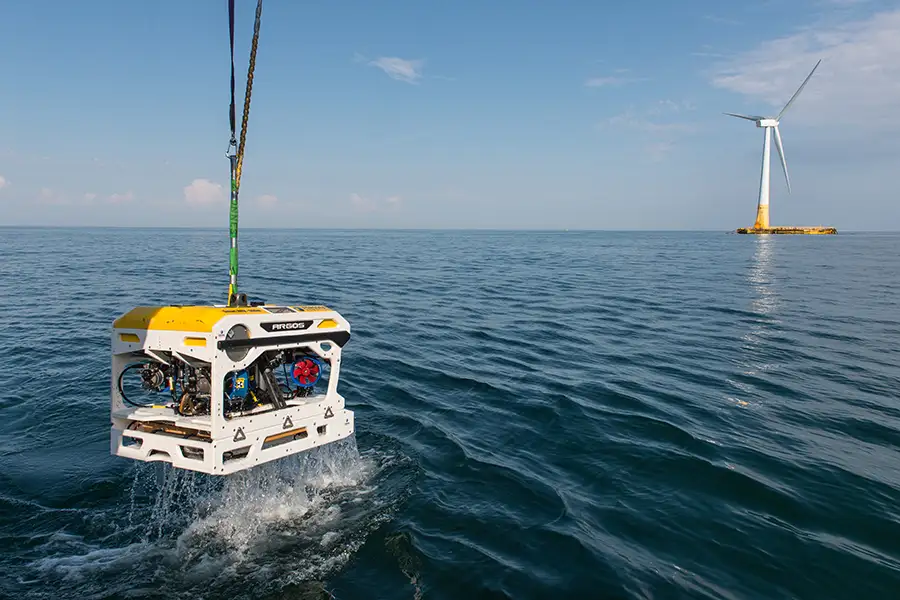
Figure 10. Example of ROV. Forssea Robotics has completed an underwater survey of a Floatgen floating wind turbine moored 12 nautical miles offshore the Le Croisic coast, western France. One of the main goals of the subsea survey was to visually confirm the integrity of the mooring lines. Source: Forssea Robotics.
Current Focus of the Moorings Subcommittee
Since the publication of the first White Paper, the focus of the Moorings Subcommittee has been to further develop the topic of integrity management by considering mooring system ‘robustness’ in more detail to support the wider industry’s development of standards, design tools, integrity management programmes and installation/operation procedures. The final goal is to improve readiness for commercial scale.